![]()
LABSI
2018/2019
Students:
Filipe Chen (1160642)
1160642@isep.ipp.pt
José Antunes (1161055)
1161055@isep.ipp.pt
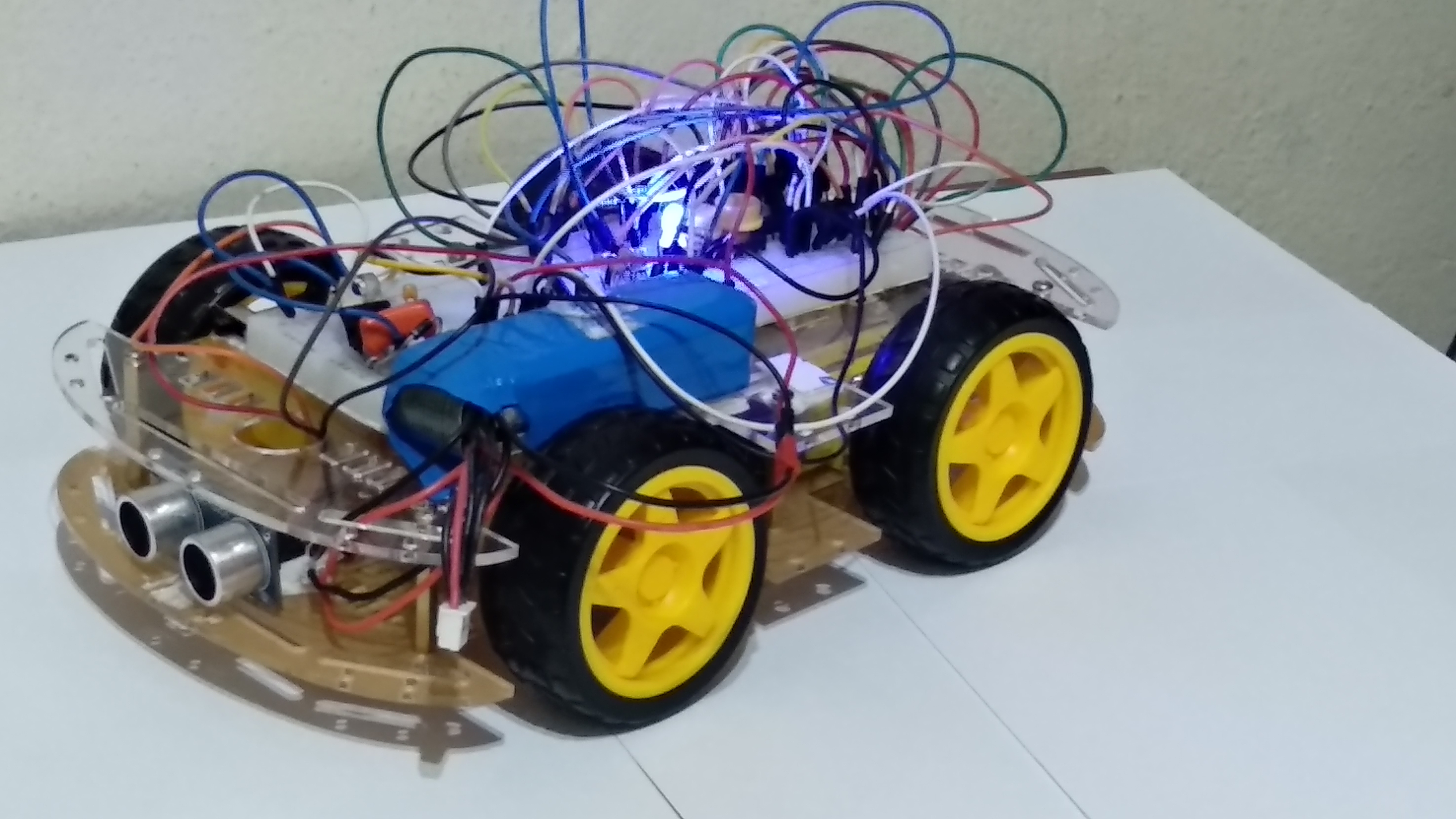

We also added the possibility to control the RC using an android App developed by us, like the typical RC. Finally we used ultrasonic sensor in order to make the car detect obstacles and stop, making the control a little autonomous.
• Autonomous Guided Vehicle (AGV)
An AGV is a portable robot that follows markers or wires in the floor, or uses vision, magnets, or lasers for navigation and collision avoidance. They are most often used in industrial applications to move materials around a manufacturing facility or warehouse.
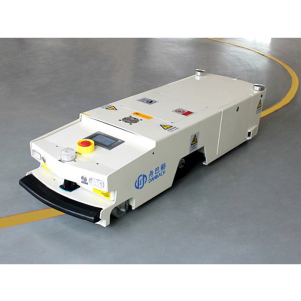
However, in our project we’re adopting the method of collision avoiding, by using ultrasonic sensors, as a component of the robot to simply avoid objects and not map the surroundings

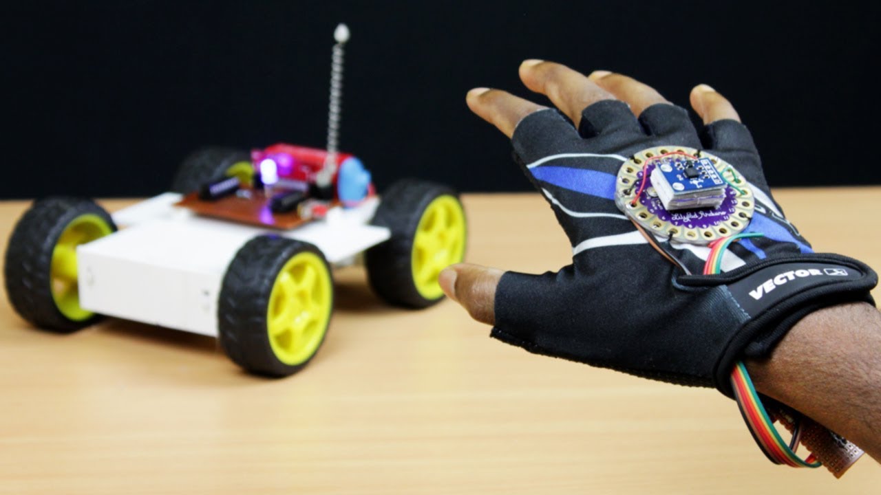
• Motion sensor(Accelerometer)
Accelerometers can be used to measure vehicle acceleration, they can also be used to mesure vibrations on machines, buildings, process control systems and safety installations.
In our project we will use the acclerometer to mesure the angles of the X and Y axis in order to make the car move in the desired direction.
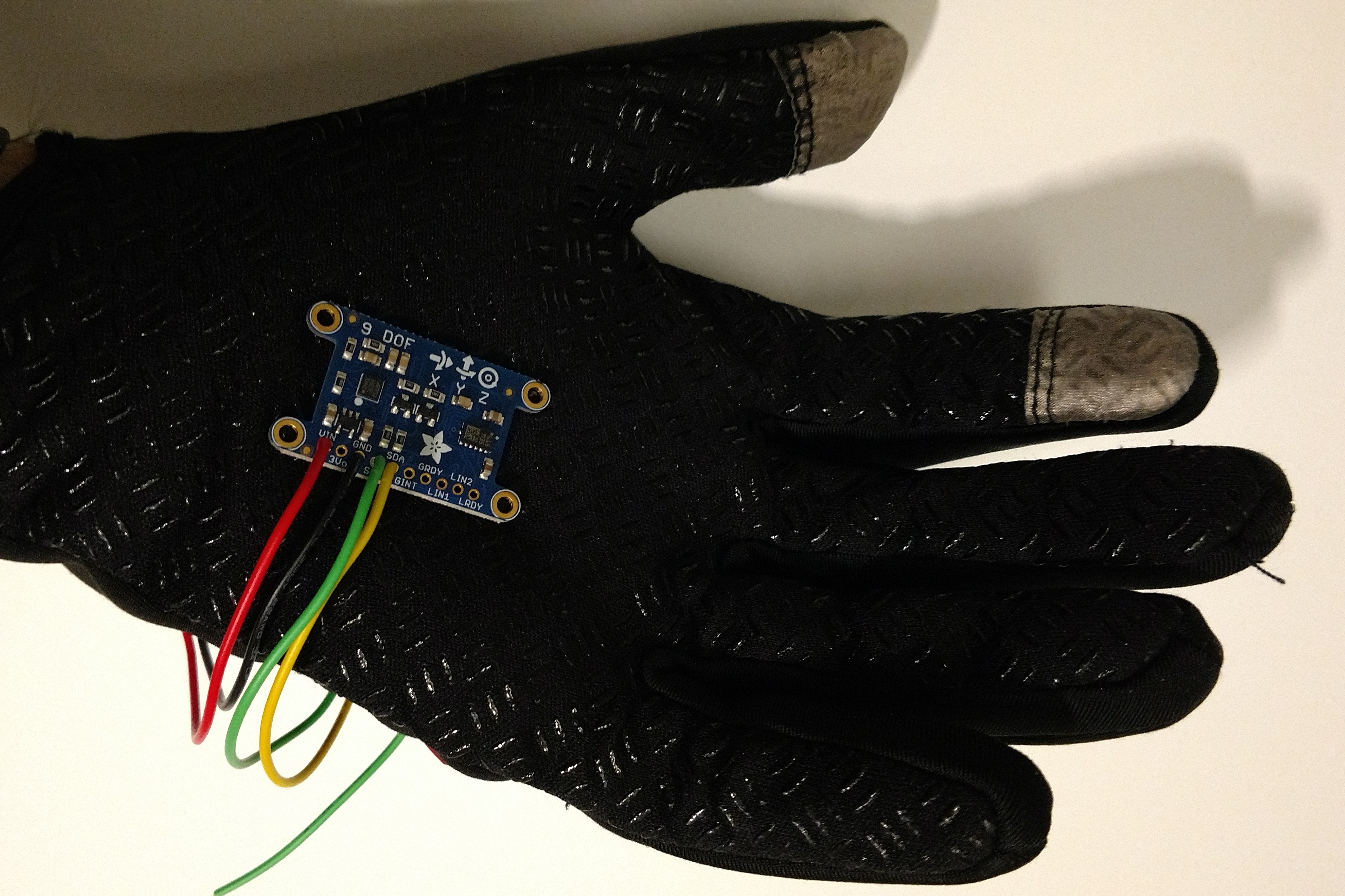
We putted the accelerometer in a glove in order to control the car using hand gestures.

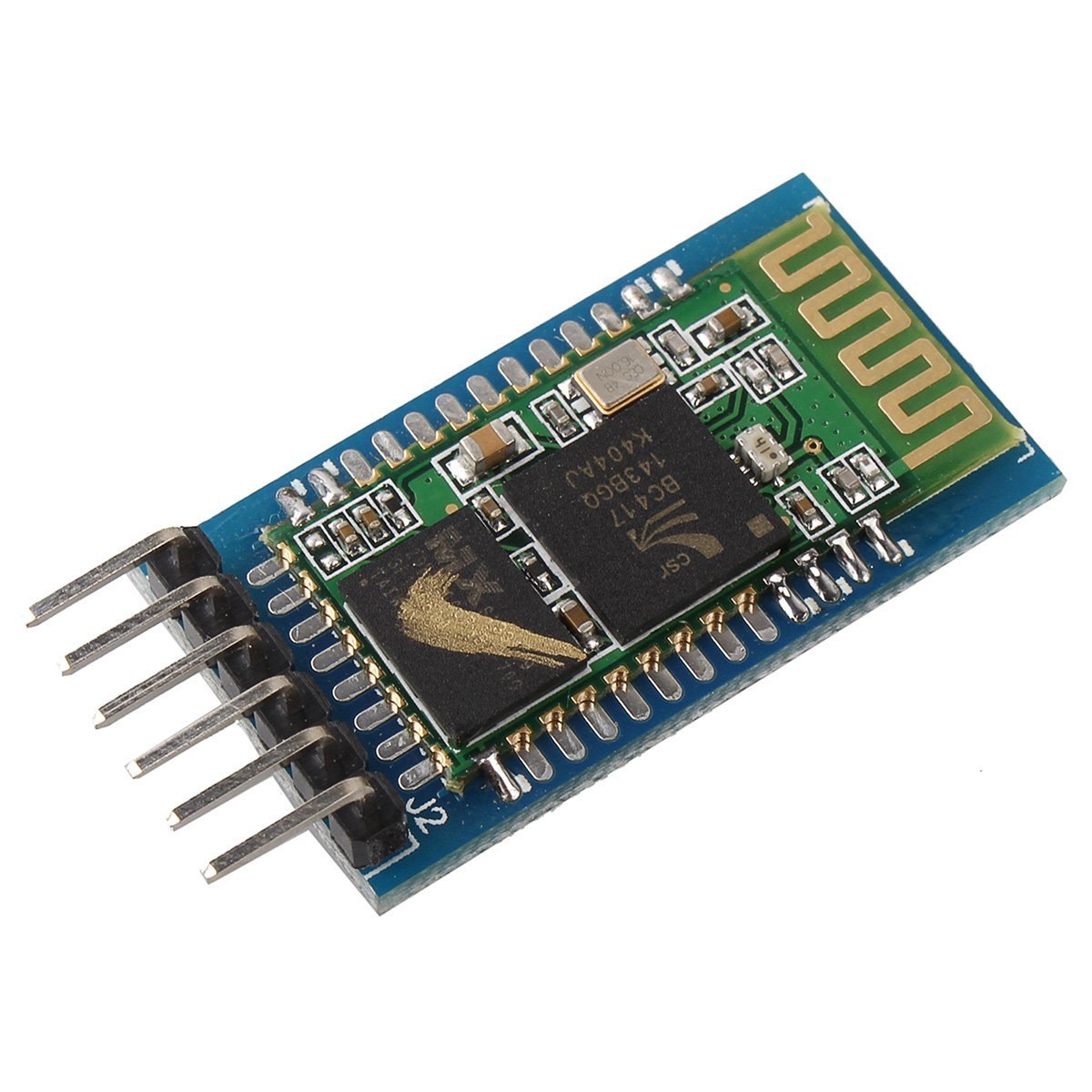
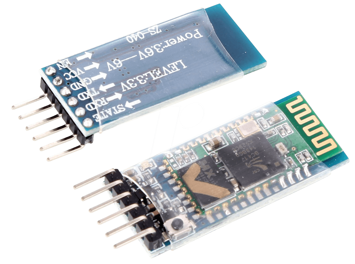
• Bluetooth
In the current decade, since the surface of Internet of Things it has rapidly grown and nowadays it’s a major theme of development by the most renown enterprises, furthermore the most noticeable feature is its wireless features.
We can find Bluetooth in almost everything related to technology nowadays like cars, phones, computers, watches, etc…
The main reason why we used bluetooth has communication device is because it is efficient and robust wireless method, easy to work with since it uses USART asynchronous mode and in addition, there are many projects related to the course in which Bluetooth is used[4], most of them use Arduino as the interface, which means that we know that it’s possible to interconnect microprocessors.
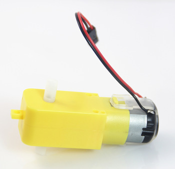
• DC Motors and H-Bridge
In order to make the car capable of moving we used DC Motors since its a motor really easy to use because we only need to apply a DC voltage at his terminals.
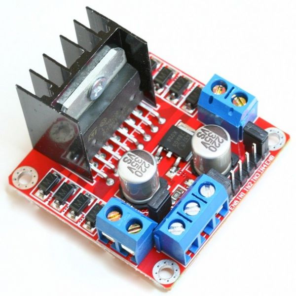
To control the direction and the speed of the DC Motor we used the typical H-Bridge.
An H-Bridge is an electronic circuit that switches the polarity of a voltage applied to a load. These circuits are often used in robotics and other applications to allow DC motors to run forwards or backwards.
These H-bridge circuits are abundant in the internet in a lot of Arduino projects due to the safety it provides.[5]

•Power Part Blocks Car/Glove Systems
• 9V Battery - It's responsible for powering all glove components, LCD, Accelerometer, etc... We used a normal comercial 9V battery since the Glove system doesn't need much current.
• Voltage Regulator Glove - Has the same objective as the Voltage Regulator from the car, downgrading the 9V to 5V in order to be possible to power all the Glove components. We also used the LM7805.
•Brain Block Car/Glove Systems
• Glove Microcontroller - Its also the main piece of the Glove system, its responsible for sending information to the LCD, receiving the values from the accelerometer and foward those values to the bluetooth module.
•Movement Blocks Car System
• Obstacle Avoidance Block Car System
• ON/OFF Blocks Car/Glove Systems
• ON/OFF Bluetooth Glove and Reset Car's Bluetooth - This Block is a switch connected to the microcontroller using an I/O Pin with an external interrupt, when the switch is pressed we send a character to the Car microcontroller to Restart the Bluetooth module in order to break the communication between them. After that, using a BJT has a switch we turn the Bluetooth Module from the Glove Off, until that same switch is pressed again in order to turn it on.
• LED Block Car/Glove Systems
• Communication Block Car/Glove/Smarthphone Systems
• Glove Bluetooth - This block is similar to the previous one, but the Module is programmed to be a Master since we can´t connect two slaves together and only communicates with the Bluetooth Module from the Car. It is used to send the accelerometer values to the other microcontroller and receive the battery levels in order to show them in the LCD. It's also used the HC-05 Module.
• Phone Bluetooth - It´s the same as the previous one but instead of sending the accelerometer values it sends the joystick position values.
• Accelerometer Block Glove System
• Display Block Glove System
• App Block Smarthphone System
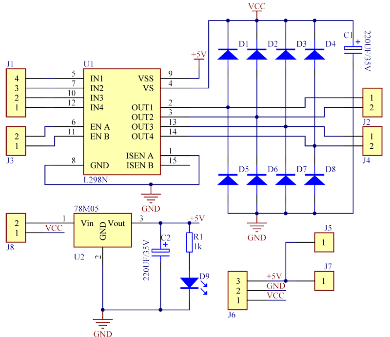
• Circuits Schematics


• x1 LI-PO Battery 11.1V 2200mAh;
• x1 ATMEGA 88;
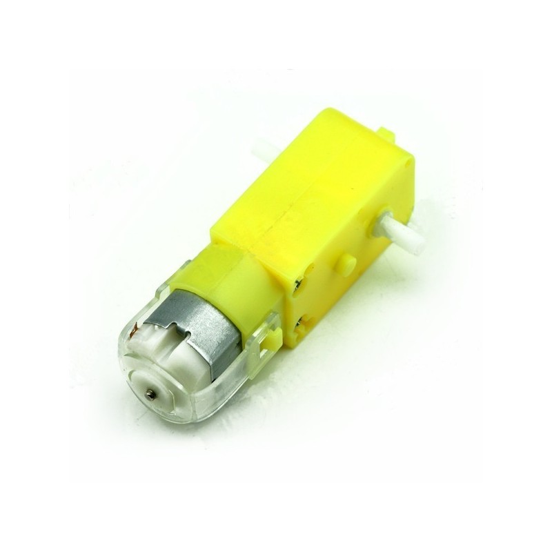
• x4 DC Motors 3V-12V;
• x1 L298N Module;
• x1 HC-05;
• x2 HC-SR04;
• x1 LM7805;
• x2 Switches;
• x1 ON/OFF Switch;
• x1 Blue LED;
• x1 2N2222;
• x1 1N4004;
• x1 0.33uF Capacitor;
• x1 0.1uF Capacitor;
• x5 1k Resistor;
• x1 0.220k Resistor;
• x1 4.7k Resistor;
• x2 10k Resistor;
• x1 9V Battery;
• x1 ATMEGA 88;
• x1 HC-05;
• x1 LCD 16X2
• x1 ADXL335
• x1 LM7805;
• x2 Switches;
• x1 Blue LED;
• x1 2N2222;
• x1 1N4004;
• x1 0.33uF Capacitor;
• x1 0.1uF Capacitor;
• x4 1k Resistor;
• x1 0.220k Resistor;
• x2 10k Resistor;
• x1 2.2k Resistor
• x1 0.680k Resistor
• ATMEGA88

• DC Motors
Those Motors work with a voltage between 3V and 12V, they have a gearbox ratio of 1:48, 200 RPM at 6V and a no load current of 200mA at 6V, unfortunately we dont have the values announced in the datasheet for the 12V.
• L298N
It is capable of controlling two DC Motors separately, since we had 4 DC Motors, they are paired 2 on each side in parallel, that way we could control the 4 DC Motors with only one L298N.
The L298N is capable of a max voltage of 40V, since our Motors working voltage is 12V it serves its purpose and it can give a max peak current of 3A.
Since we didn´t want to spend a lot of space in our Breadboard assembling the L298N circuit with the capacitors and the flyback diodes we opted to use an already made module.
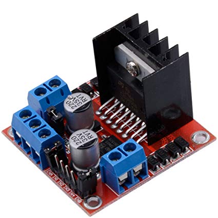
It is a really cheap and easy to use module, making it the perfect choice for our project.
• HC-SR04
It is powered with a voltage of 5V and has an operation current of 2mA. Unfortunately it only has an action angle of 15°, meaning that after that angle the sensor will not work properly.
It is not an high quality sensor, making it the Achilles' heel of our project, but it is a cheap and easy to use sensor.
The work principle of the sensor is the following:[6]
1º - We send to the Trigger Pin an High Logic Level during at least 10us;
2º - After that the sensor sends automatically eight pulses of 40kHz;
3º - After the eight pulses are sent the sensor makes the Echo Pin High Logic Level;
4º - If the pulses find an obstacle they are reflected, being captured by the receptor, making the Echo Pin Low Logic Level again;
5º - With the time that we measured between the High Echo Level and the Low Echo Level, we can calculate the distance in centimetres using this formula: (Microcontroller Thicks)/(466.47);
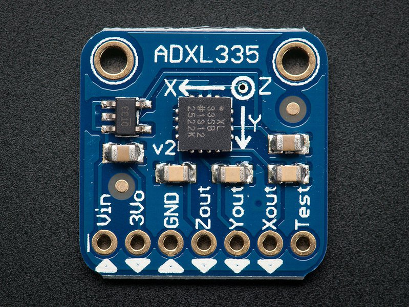
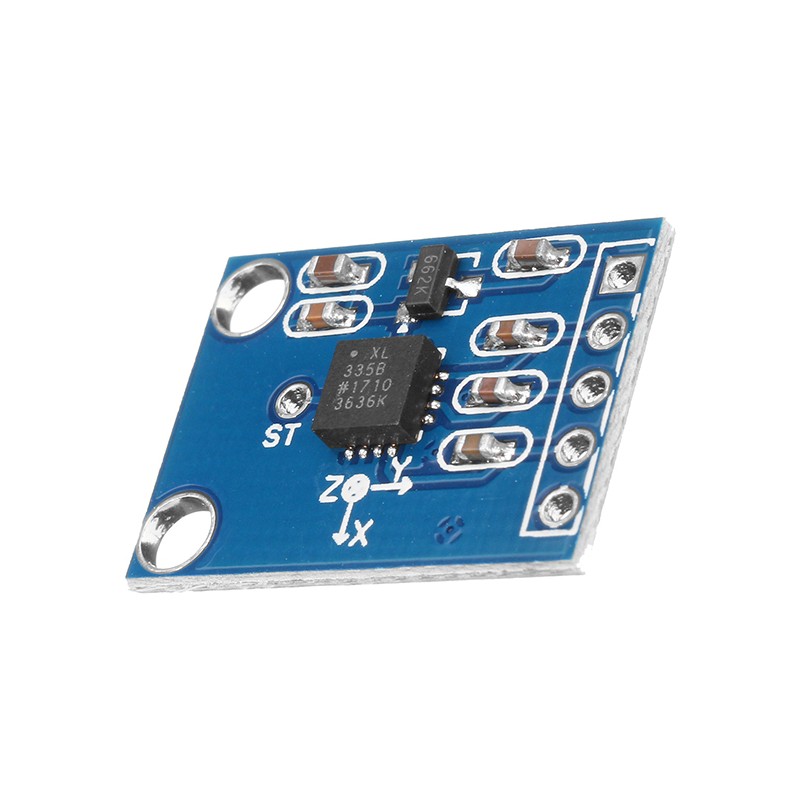
• ADXL335
It can measure acceleration values between -3g and 3g emitting a analog voltage between 0V and 3V, making it perfect to use with the ADC of the microcontroller.
With this accelerometer we can measure the angle our hand is doing and with those values we make the car move in the desired direction.
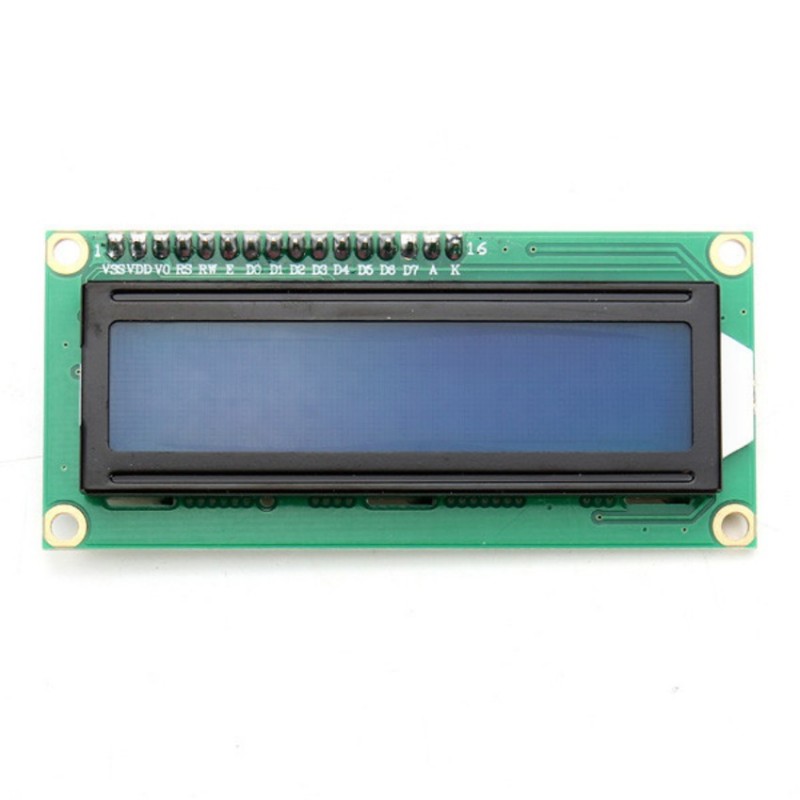
• LCD 16X2
It can be used with I2C communication, 4 bits or 8 bits, in our project we are using the 8 bits mode since we found a really easy to use library in which we only changed some code.[7]
The LCD has a working voltage between 4.5V and 5.5V and a current between 1mA and 1.5mA. It also has a Backlight voltage between 1.5V and 5.5V and a current between 75mA and 200mA depending on the brightness.
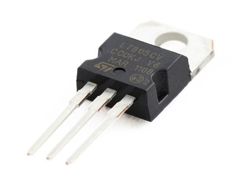
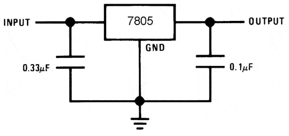
• LM7805
It can regulate voltages from 7V to 25V giving an output voltage between 4.8V and 5.2V, the maximum output current this regulator can supply varies between 1A and 1.5A, it also has a maximum dissipated power of 15W.
It's recommended to use a temperature dissipator with this component but since we dont need high levels of current in our circuit we dont have the need to use one.


• Function Explanation
USART RX Interupt function - Receives the data from the other devices and check which device is communicating and what we need to do with the data received.
External Interrupt 0 and 1 functions - This functions are identical, the only difference between them is that one is for the front ultrasonic the other is for the rear one. In this function we start or stop the timer whenever the sound wave is launched or received, after that we calculate the distance and if it is less than 50 cm we stop the car.
Glove and Phone Movement functions - This functions are also identical, with the data received from the other devices they decide the speed and the direction of the motors.
Send Messagem function - Used to send data from this microcontroller to the other devices, such has battery level.
Timer 1 interrupt function - Responsible for making every time count in our program for example the blink Led.
Main function - In the main we see if the car needs to brake, we also start the ultrasonic sensors depending on the direction the car is going and reset the bluetooth module if requested by the glove.
External Interrupt 0 function - Here we check if the switch to turn the bluetooth ON/OFF is pressed.
Glove movement function - This function decides what speed and direction we should display in the LCD but only if there is communication between the car and the Glove.
Timer 1 interrupt function - This has the same job has the one from the car.
Main function - In the main function we check if the Glove is connected to the car, and if it's connected, the ADC of the car reads the values from the accelerometer and fowards them through bluetooth to the car. It also checks if the turn OFF flag is activated, and assuming that it's activated, the microcontroller sends a message to the car in order to reset the bluetooth module, and turns the glove bluetooth module off. The function also checks if there's some error in the communication, and case there is any error, it prints error message in the LCD and turns the bluetooth module off.
• Initializations

TCCR0A chooses Clear timer on Compare mode.
TCCR0B put the prescaler to 64 so we get comfortable frequency with clock at 8Mhz.
TIMSK0 enables the Output compare MatchA Interrupt .
- USART:

UCSR0A Define the speed accordingly to the baudrate we chose.
UCSR0B Enable Receiver and Transmiter and Receiver Interrupt.
UCSR0C put the prescaler to 64 so we get comfortable frequency with clock at 8Mhz.
- ADC:
ADCMUX Select PIN to read from.
ADCSRA Enables the AD Converter and ADC’s Interrupt and set prescaler at 64 for optimal frequency.
- External Interrupt Switch ON/OFF Bluetooth Module /Break connection:
EICRA Set falling edge on interrupt 0 for the switch.
EIMSK enable Interrupt0.
• Car Initializations:

- Timer/Counter 0 (Fast PWM Movement Control):
TCCR0A Define the Fast PWM and prescaler 64.
TCCR0B Define the non inverting mode for timers A and B.
- Timer/Counter 1:
TCCR1B Set timer to Clear timer on compare with a prescaler of 8.
TIMSK1 Enable Interrupt.
- Timer/Counter 2 Ultrasonic sensor counter:
TIMSK2 Enable interrupt of Overflow, enters when TCNT overflows.
TCCR2A/B are 0 because we only activate whenever we need this timer.
- External Interrupt Ultrasonic sensor Interrupt:
EICRA set this to activate interrupts whenever there’s a logical change.
EIMSK is only activated whenever we need it.
- Pin Change Interrupts for the buttons:
PCICR we enable 2 of its interrupts.
PCMSK0 Set the pin which activates pin change Interrupt0 Turn ON/OFF Ultrasonics.
PCMSK1 Set the pin which activates pin change Interrupt1 Turn ON/OFF Instant Stop.


Although we had planned to implement PCB for the glove, we didn’t succeed putting it to work thus we adapted the breadboard to function as a glove. This is one of the aspects to be improved upon as we didn’t adapt the Pin connections to ease the board layout.
We had a lot of problems on the side of software and hardware throughout the development as we had vast amount variables and interrupts conflict with each other, and on the other side we used almost all our available pins on each microcontroller and the Ultrasonic sensors aren’t the ideal obstacle detector because if the incidence angle is a bit high the wave will reflect outside of the receiver zone and thus not detecting the obstacle which results in the car hitting the wall.
[1] Tapendra Mandal-How to Make a Gesture Control Robot at Home, https://www.youtube.com/watch?v=rejZmqRrKMc
[2] Tony Canning-Arduino Wall Avoiding Robot, https://www.instructables.com/id/Arduino-wall-avoiding-robot-FabLab-NerveCentre/
[3] Chirag Gupta, Nitin Garg - International Journal of Electronics, Electrical and Computational System Volume 3, Issue 9 November 2014, http://academicscience.co.in/admin/resources/project/paper/f201411261416991775.pdf
[4] Dejan-Arduino and HC-05 Bluetooth Module Tutorial, https://howtomechatronics.com/tutorials/arduino/arduino-and-hc-05-bluetooth-module-tutorial/
[5] John Boxall- L298N Dual Motor Controller Module 2A and Arduino https://tronixlabs.com.au/news/tutorial-l298n-dual-motor-controller-module-2a-and-arduino/
[6] Ultrasonic Module HC-SR04 interfacing with AVR ATmega16/ATmega32 https://www.electronicwings.com/avr-atmega/ultrasonic-module-hc-sr04-interfacing-with-atmega1632
[7] Ligo George- Interfacing LCD with Atmega32 Microcontroller using Atmel Studio https://electrosome.com/interfacing-lcd-atmega32-microcontroller-atmel-studio/